|
||
         |
Texturemapping 3D Aircraft
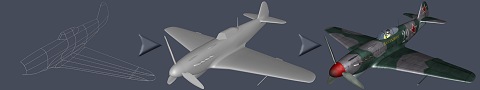
This tutorial explains how you can texture a 3D aircraft model. It's written in such a way that even relative beginners to Max might be able to follow this tutorial with some success. For this tutorial I will use my Yak-9D model as an example. Images of the finished model can be found here. Before you start texturing you need a model. I prefer to build my aircraft models using Surface Tools. I might do a tutorial on that later. For now just watch the little animation to get an idea of the process (Figure 1).
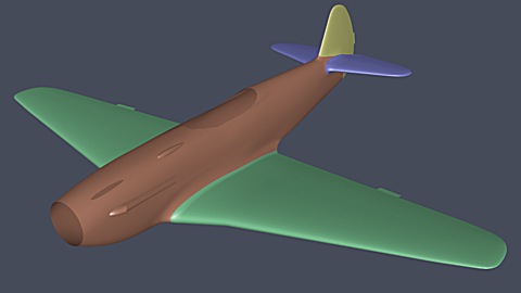
Figure 1 - Click on the image to view the animation What you do is make a so-called splinecage, and add a Surface modifier to it. This feature is only available in Max 3.0 or greater, or in 2.5 as a seperate plugin. When your model looks ok, you can collapse it to an Editable Mesh and add detail to it and fix any parts that were difficult to model with splines by building new faces, so-called polymodelling. I won't go into details here. PLEASE NOTE: When your mesh is finished, you want to texture it, of course. Basically what you do is to divide the model in different parts and texture them seperately. The body, tail and wings of my Yak-9 were all merged into one mesh, so what I did was to give each area that needed different texture-mapping a different Material ID. For example:
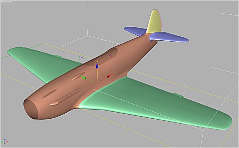
Figure 2 - Every part gets its own Material ID First select all polygons that make up the wing. Set their Material ID to 2. Then without leaving Edit Mesh Polygon Subobject, add a UVW Map modifier. It should be set to Planar in such a way that it outlines the wings (most likely XY). Press fit to make sure it fits the wings tightly. Leave the UVW set to 1, as all texturing will use UVW1. Notice the direction in which the Gizmo points. In subobject mode you can rotate it 90 degrees to align your texture horzontally or vertically, depending on what your prefer. Press Fit again to make it fit tightly. You now have mapped your wing (Figure 3).
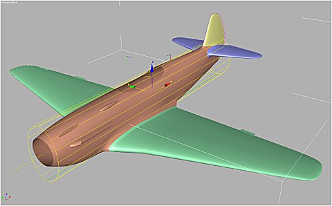
Figure 3 - Use planar UVW mapping for the wings Next add an Edit Mesh modifier again, and this time select all tailplane faces. Change their Material ID to 3. Without leaving Subobject mode, add another UVW Map modifier and again select Planar XY, align the Gizmo to your wishes, press Fit and leave UVW set to 1. Again add an Edit Mesh modifer, select the left hand tailplane, set ID to 4 and add a Planar UVW map to it. Of course repeat this for the right hand side, but don't forget to set Material ID to 5. Now you've done the easy parts: planar mapping all the wing surfaces. Now comes the fuselage, which can get a bit more complicated. Again add an Edit Mesh modifer and select all faces that have a material ID that's set to 1. These faces should now make up the fuselage of the plane. Without leaving Subobject mode, add another UVW Map. This time set it to cylindrical. Get the gizmo so to align along the length of the fuselage. A cylindrical map has a seam, which shows up as a green line in your gizmo. Make sure to rotate your gizmo so the green line is at the bottom of the plane. This allows for easier texturing later, as the bottom of a plane often has a uniform colour, and the seam is less likely to show up. While still in Gizmo Subobject mode, apply some Non-Uniformal Scaling to your gizmo, so it fits the frontview of the fuselage better (Figure 4). This way texture stretching is less likely to occur.
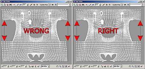
Figure 4 - Use cylindrical UVW mapping for the fuselage Still there always will be a bit of stretching. To avoid this, the texture has to be tweaked. Add a UVW Unwrap modifier to your model's modifier stack. Click Edit. If the cylindrical texturing was perfect, the mapping should be symmetrical. Often however some faces 'jump' to the wrong side (Figure 5). This is no big problem though, as long as the map tiles (which is a default setting in Max). If you wish to fix this however, delete the UVW Unwrap again and in the UVW Map modifier and rotate your gizmo a fraction of a degree. Add a UVW Unwrap modifier again and check if you did it right. Now if the mapping is symmetrical (Figure 5), you can start exporting your UVW mapping to bitmaps and start making the textures. Without textures it is difficult to tell how bad the stretching will be.
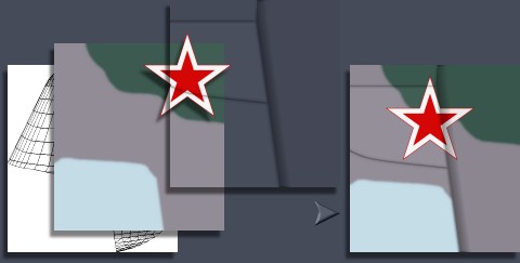
Figure 5 - Correct cylindrical UVW unwrapping To export the textures, you could use either of the gollowing plugins: Unwrapping the texture to a bitmap requires you to decide what the sizes of your texture will be. If you are going for close-ups, or work that has to be printed, you'll need a high resolution texture to keep the looks of the model detailed and crisp. If you only need to make web-based images or a model for an animation, texture sizes don't need to be so big. It's something you have to decide for yourself. As a rule of thumb, your texture should be at least as big, or even twice as big as it will show up in your biggest render or greatest close-up. Thus every pixel in your texture must be smaller then every pixel in your rendered output. Go back to every UVW Map modifier and write down the length and width of every UVW map. For the cylinder, multiply the diameter by Pi (3.142) to get the width of your texture. Now with the plugin installed, go to the utilities panel and select the unwrap plugin. For width and height enter the values you just wrote down, multiplied by a fixed value you chose yourself that will finally resemble your texture size in pixels. Don't make your texture too small, as it is easier to scale a texture down after you're done, then to re-do it completely when your texture size proves inadequate! In the Unwrap Util check Use Material ID and of course matched those to the parts who's UVW mapping you are exporting. After this is done for every part, you can use this bitmap as the background layer of your textures. Use the bitmap editing program of your choice for editing. Most use Photoshop, but I personally prefer Paint Shop pro as it is very quick and easy to use, while still offering great paint tools. Make a multilayer texture, using each layer to resemble different parts in the texture. I usually start with the wireframe that was just exported, then add a diffuse layer, which basically is the camouflage of the plane. Add a layer for panellines, another one with greyscale panels (with layer properties set to Hard Light) to break up the evenness of the texture, a weathering layer with stains and stuff like that and another layer for metal chips. Add more layers if you wish. Instead of using the PSD file as a texture, it's much faster to save a flattened copy of it as a JPG, TGA or TIFF file. From your main texture you can derive bumpmaps and shininess maps and such and save them as a greyscale GIF files. A simplified example of a diffuse texture build-up is shown in Figure 6.
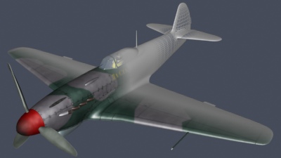
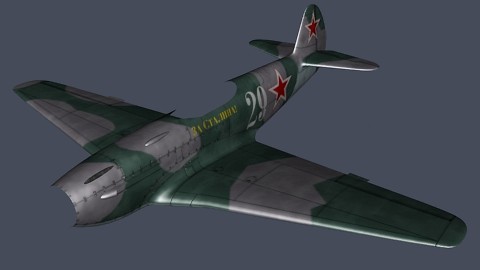
Figure 6 - Layered texture based on the wireframe bitmap With the basic textures ready, map them on your model using a Multi-Subobject material. Give it five slots that corresponds with the UVW mapped parts. For the wing and the tailplane use a Top-Bottom material set to Coordinates set to Local. Blend a bit to make the top and bottom texture to nicely blend into eachother (as most aircraft are spray painted) and adjust Position to your wishes. For the textures, simply use Explicit UVW mapping with UVW channel set to 1. Click the Show Map in Viewport button to preview the alignment of your texture. Make a few testrenders to see if any stretching occurs. Likely the wings will be fine, but the fuselage will need some tweaking. Instead of skewing your texture, select your model and click Edit to make adjustments to the UVW map. Use the Soft Selection spinner to scale or move larger parts of your model's vertices to fix the stretching in the UVW mapping. When all this is done you can resume finishing your texture maps and adjusting the material properties (Figure 7).
Figure 7 - The textured plane I hope this tutorial is of help to those who want to texture airplanes, but also to those who have built other more complex models. If you have any suggestions to improve this tutorial, please let me know by e-mail. If this tutorial was helpful for you, I'd love to hear it too, of course. Happy texturemapping! Ronnie Olsthoorn |
|